Buffer fluid systems

Each rotating pump has a drive shaft that has to be sealed in some form. Sealing can be performed through a magnetic coupling, a stuffing box packing, a viscoseal with reverse conveyance thread, a single or double working mechanical seal, a multiple lip seal or through combinations of the previously named systems.

For certain batch processes (for example, with the production of polyester), the shaft seal must be made with difficult conditions. On the one hand, the temperature, speed of the pump and viscosity change during a batch; on the other hand, the pump shaft is sealed off against high vacuum on the suction side. Under these conditions, only double-acting, locked seal systems can be used; either a double stuffing box or a double mechanical seal in “back to back” or “face to face” arrangement.

Both systems have to be supplied with a buffering fluid. This must be compatible with the transport product (in our example polyester) and temperature-resistant, because normally there are temperatures between 280°C and 300°C in the polyester production process.

The two illustrated supply systems are different

I) through a dynamic buffer fluid system and
II) through a static buffer fluid system.

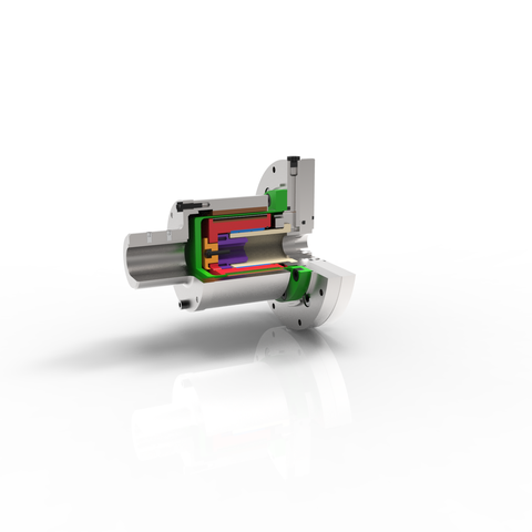
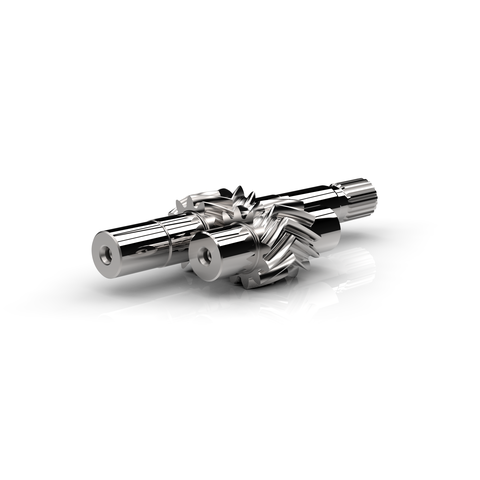
Both systems contain a magnet-driven gear pump that ensures a forced circulation of the buffering medium. The operating temperature may amount to up to 350°C.

Landscape

Dynamic buffer fluid systems

The system I (the dynamic system) is used if the pressure on the suction side varies relatively strongly. It is recorded with the pressure sensor (10) and moves the control valve (12) on the output of the mechanical seal (9) through control electronics (11). Depending on the setting of the control valve (12), the gear pump (6) pumps the buffering medium against the more or less closed control valve (12). A buffering pressure starts, which is an adjustable differential pressure above the suction pressure of the polymer pump (8). The dynamic buffering pressure is generated by the gear pump (6) for this system. The pipes under the buffering pressure are identified with an “A”, the pipes under the atmospheric pressure with a “B”. Buffering medium tank(2) is operated here without pressure.


Landscape

Static buffer fluid systems

The system II is used if the pressure on the suction side of the pump (8) continues to remain constant. The buffering medium tank  (2) is impinged with nitrogen through the connection (13). The buffering pressure is generated through the nitrogen pressure. The gear pump (6) must only make up for the pipe losses. The entire system including the buffering medium tank (2) is under nitrogen = buffering pressure here. With the hand refill pump (1), the level in the buffering medium tank can be increased if the level switch (3) shows a low level and triggers an alarm.

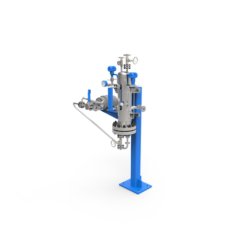
Example: Buffer fluid system according to customer requirements (API specification)

  • WITTE circulation pump
  • Pressure container
  • Exhaust flange
  • High pressure inspection glass
  • Pressure transmitter
  • Differential pressure transmitter
  • Pressure gauge

  • WITTE circulation pump

    Circulation of the buffering medium.

  • Pressure container

    Container with 30 l volume. Can be used up to 400 °C degree operating temperature.

  • Exhaust flange

  • High pressure inspection glass

    High pressure inspection glass with buffering fittings

  • Pressure transmitter

  • Differential pressure transmitter

  • Pressure gauge

[Translate to English:] Sperrsystem nach Kundenvorgabe